You can connect a BTS7960 motor driver to an Arduino and control high-power DC motors with just a few easy steps. This motor driver works with a motor supply voltage from 6V to 27V and handles up to 43A of continuous current. The table below shows key specifications that help you use it in beginner-friendly projects:
| Specification | Value |
|---|---|
| Motor Output Voltage | 6V – 27V |
| Logic Input Voltage | 3.3V – 5V |
| Continuous Output Current | 43A |
| Peak Output Current | 43A |
You get built-in protection features and smooth speed control using PWM signals. You can safely control both speed and direction with Arduino.
Key Takeaways
-
The BTS7960 motor driver lets you control high-power DC motors safely and easily with Arduino.
-
Use the correct wiring and power connections to activate built-in protection and ensure smooth motor control.
-
Control motor speed and direction by sending PWM signals from Arduino to the BTS7960’s input pins.
-
Always double-check your wiring and test your setup with simple code before running your motor.
-
Add cooling like heatsinks or fans if your motor draws high current to prevent overheating and damage.
What You Need

Components
You need a few basic parts to get started. Here is a list of the main components:
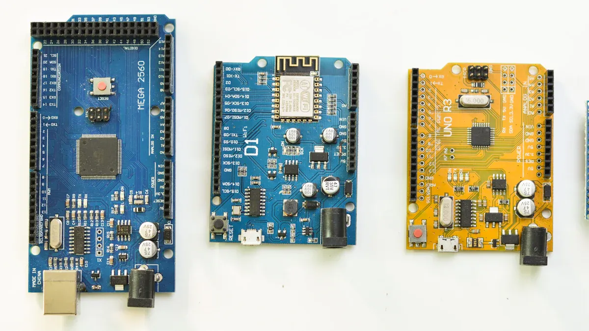
-
Arduino board (Uno, Mega, or Nano)
-
BTS7960 motor driver module
-
DC motor (6V–27V, depending on your project)
-
External power supply (matching your motor’s voltage and current needs)
-
Jumper wires (male-to-female and male-to-male)
-
Breadboard (optional, for easy connections)
Tip: Always check the datasheet for each component before connecting. This helps you avoid wiring mistakes and keeps your project safe.
Below is a table showing common performance benchmarks and reliability ratings for electronic components. These ratings help you choose the right parts for your project, especially if you need higher reliability or plan to use your project in tough conditions.
| Performance Benchmark / Rating | Description | Key Features / Tests | Reliability Impact |
|---|---|---|---|
| Commercial Grade | Manufactured to datasheet specs only, flexible design and testing | No mandatory qualification or testing; focus on cost/performance trade-off | Baseline reliability for general use |
| Automotive Grade (AEC-Q200) | Stress test qualification by Automotive Electronics Council | Tests at various temperatures; graded 0 to 4 based on pass/fail; no retesting if unchanged | Suitable for automotive applications with graded reliability |
| COTS-Plus | Commercial standard product up-screened with MIL-PRF-like testing | Reduced infant mortality rate; increased reliability; options for surge current and group testing | Higher reliability than standard commercial grade |
| IECQ-CECC | European qualification for high-reliability markets (aerospace, military) | Routine periodic testing (visual, dimensions, solderability), rolling test program (thermal shock, operational life), facility audits | Ensures consistent quality; authorized distributors only |
| MIL-PRF | US Military performance specification | Manufacturer on QPL; strict QA; lot basis testing; failure rate levels (M=1%, P=0.1%, down to V=0.001% for space) | Predictable quality and failure rates; includes surge current screening for tantalum capacitors |
| ESCC QPL | European Space Components Coordination Qualified Parts List | Fully evaluated and qualified space components; strict design and process control; additional testing like LVT and LAT | High assurance for space applications |
| EPPL | European Preferred Part List | Components suitable for space missions but not fully space qualified | Broader availability but lower qualification than ESCC QPL |
Tools
You will need some basic tools to build your project:
-
Small screwdriver
-
Wire stripper and cutter
-
Multimeter (for checking connections)
-
Soldering iron and solder (if you want permanent connections)
-
Safety glasses
These tools help you make accurate and reliable connections. Many users have found that quality tools last longer and give better results. For example, tools designed for quality control, like those developed by Kaoru Ishikawa, use simple methods to solve problems and improve accuracy. Over time, these tools have proven their durability and precision in many fields, from education to engineering. When you use the right tools, you can work faster and avoid mistakes.
BTS7960 Motor Driver Wiring
Pin Mapping
Before you start wiring, you need to know which pins on your Arduino connect to the BTS7960 motor driver. The BTS7960 module has several input pins that control the motor’s speed and direction. Here is a common pin mapping you can use:
Example Arduino to BTS7960 pin mapping:
RPWM → Arduino pin 3 (PWM output)
LPWM → Arduino pin 5 (PWM output)
R_EN → Arduino pin 2 (Enable pin)
L_EN → Arduino pin 4 (Enable pin)
The RPWM and LPWM pins receive PWM signals from the Arduino. These signals control the speed and direction of your motor. The R_EN and L_EN pins act as enable switches. You must set them HIGH to allow the BTS7960 motor driver to operate. The module also includes current sense pins (R_IS, L_IS) for diagnostics, but you can leave these unconnected for basic projects.
The BTS7960 motor driver uses logic-level inputs. This means you can connect it directly to Arduino pins without extra components. The datasheet shows that the IN and INH pins are TTL/CMOS compatible, so you do not need special drivers. The module’s pin layout usually has two rows. The top row includes RPWM, R_EN, and R_IS. The bottom row includes LPWM, L_EN, and L_IS. Always check your module’s pin labels before wiring.
Step-by-Step Guide
Follow these steps to wire your BTS7960 motor driver to your Arduino:
-
Connect Power and Ground
-
Attach the motor power supply’s positive terminal to the BTS7960’s VCC (motor power) input.
-
Connect the motor power supply’s ground to the BTS7960’s GND.
-
Link the Arduino’s GND to the BTS7960’s logic GND. This step ensures both devices share a common ground, which is critical for proper signal transmission.
-
The BTS7960 integrates high-side and low-side MOSFETs with built-in protection. Correct power and ground connections activate these features and keep your circuit safe.
-
-
Wire the Control Pins
-
Connect Arduino pin 3 to RPWM on the BTS7960.
-
Connect Arduino pin 5 to LPWM.
-
Connect Arduino pin 2 to R_EN.
-
Connect Arduino pin 4 to L_EN.
-
Set both enable pins HIGH in your code to activate the driver.
-
The BTS7960 motor driver’s logic-level inputs make this process simple. You do not need extra resistors or buffers.
-
-
Attach the Motor
-
Connect one motor terminal to the BTS7960’s output A.
-
Connect the other motor terminal to output B.
-
Make sure the wires are secure and not touching each other.
-
-
Double-Check All Connections
-
Use a multimeter to check for continuity and correct voltage levels.
-
Perform a visual inspection to confirm wire color, gauge, and tightness.
-
Gently tug each wire to ensure it is secure.
-
If you have access to an infrared thermometer, scan the connections after powering up to check for overheating.
-
-
Test the Setup
-
Power on the system.
-
Upload a simple test sketch to the Arduino.
-
Observe the motor’s response. If the motor does not move, check your wiring and code.
-
Tip: Always check the BTS7960 datasheet and your module’s pinout diagram before wiring. Manufacturers may use different layouts or labels. Proper wiring ensures the BTS7960 motor driver’s protection features, such as overcurrent and overtemperature shutdown, work as designed.
-
The BTS7960 motor driver’s design includes diagnostic and protection features. These features depend on correct wiring for safe operation. Application notes and technical diagrams show that reliable wiring supports heat dissipation and signal integrity. Adjustable slew rates and current sensing pins help you optimize performance and monitor the system.
-
You can use simple tools like a multimeter or continuity tester to verify your connections. For more advanced testing, use insulation resistance tests or infrared scans to detect loose or overheating wires. These steps help prevent failures and keep your project running smoothly.
Arduino Code
Example Sketch
You can control the speed and direction of your DC motor using the BTS7960 motor driver and Arduino. Here is a simple example sketch. This code lets you spin the motor forward, slow it down, reverse it, and stop it. You can copy and upload this code to your Arduino board.
// Pin assignments
const int RPWM = 3;   // Right PWM pin
const int LPWM = 5;   // Left PWM pin
const int R_EN = 2;   // Right Enable
const int L_EN = 4;   // Left Enable

void setup() {
  pinMode(RPWM, OUTPUT);
  pinMode(LPWM, OUTPUT);
  pinMode(R_EN, OUTPUT);
  pinMode(L_EN, OUTPUT);

  digitalWrite(R_EN, HIGH); // Enable right channel
  digitalWrite(L_EN, HIGH); // Enable left channel
}

void loop() {
  // Move forward
  analogWrite(RPWM, 200); // Set speed (0-255)
  analogWrite(LPWM, 0);
  delay(2000);

  // Slow down
  for (int speed = 200; speed >= 70; speed -= 10) {
    analogWrite(RPWM, speed);
    delay(100);
  }
  delay(500);

  // Stop
  analogWrite(RPWM, 0);
  analogWrite(LPWM, 0);
  delay(1000);

  // Move backward
  analogWrite(RPWM, 0);
  analogWrite(LPWM, 200);
  delay(2000);

  // Slow down
  for (int speed = 200; speed >= 70; speed -= 10) {
    analogWrite(LPWM, speed);
    delay(100);
  }
  delay(500);

  // Stop
  analogWrite(RPWM, 0);
  analogWrite(LPWM, 0);
  delay(1000);
}
🛠️ Tip: PWM values range from 0 to 255. Many motors need a minimum PWM value (like 70) to start moving. If your motor does not spin at low values, try increasing the starting PWM.
You can use for loops to change speed smoothly. This makes the motor accelerate or decelerate without sudden jumps. The code above uses this method for both forward and backward movement.
-
PWM values from 0 to 255 give you fine control over speed.
-
You can adjust the delay times to change how long the motor runs in each direction.
-
The enable pins must stay HIGH for the BTS7960 motor driver to work.
How It Works
The Arduino sends PWM signals to the BTS7960 motor driver. These signals control how much power the motor receives. You use the analogWrite() function to set the PWM duty cycle. A higher value means more power and faster speed.
| Evidence Aspect | Description |
|---|---|
| PWM Speed Control | Arduino uses analogWrite() to set PWM duty cycle for precise speed control. |
| Direction Control | Digital pins set HIGH or LOW to choose motor direction. |
| Testing Tips | Start with low speeds to check wiring and avoid mistakes. |
| Hardware Integration | The BTS7960 motor driver acts as an H-Bridge to reverse current and direction. |
| Practical Code Example | Code sets direction and PWM to spin forward, backward, or stop. |
| Reliability Confirmation | Changing PWM values and watching the motor shows reliable control. |
| Advanced Control | You can add sensors or PID control for better accuracy. |
The BTS7960 motor driver uses two PWM pins: RPWM and LPWM. When you set RPWM to a value and LPWM to zero, the motor spins one way. When you swap the values, the motor spins the other way. If both are zero, the motor stops.
The Arduino Uno has special pins (like 3 and 5) that create PWM signals using hardware timers. The analogWrite() function sets the duty cycle. For example, analogWrite(3, 128) gives about 50% power. You can measure these signals with a logic analyzer to see the actual frequency and duty cycle. Pins 3 and 5 have different frequencies, but both work well for motor control.
You can also use random values or more advanced code to make the motor move in different ways. For example, you can use the random() function to pick speeds or directions. This keeps your code simple and lets you test many behaviors without complex logic.
🔍 Note: If you want even more control, you can use libraries or write your own functions. Some libraries help you add features like acceleration curves or sensor feedback.
PWM signals can also be smoothed out with a filter to create a steady voltage. This is useful if you want to power other devices. The BTS7960 motor driver handles high current, so your Arduino code can focus on logic and timing.
You can always expand your project. Try adding buttons, sensors, or remote control. The BTS7960 motor driver gives you the flexibility to build many types of motor projects.
Troubleshooting
When you build a project with a BTS7960 motor driver and Arduino, you may face some common problems. This section helps you find and fix issues quickly.
Motor Not Working
If your motor does not move, follow these steps:
-
Check that your power supply is connected and turned on.
-
Make sure all wires are secure and in the correct pins.
-
Use a multimeter to check for voltage at the motor terminals.
-
Confirm that the enable pins are set HIGH in your code.
-
Test your Arduino by uploading a simple blink sketch to make sure it works.
-
Try swapping out the motor or driver if you suspect a faulty part.
Start with simple checks like power and wiring. Always begin from a known good state to isolate the issue.
Here is a table showing common motor problems and what to look for:
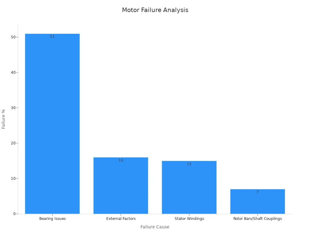
| Motor Problem | Possible Causes | Effects on Motor | Signs to Look For |
|---|---|---|---|
| Voltage issues | Power supply problems, bad circuits | Motor does not start, gets hot | No movement, heat, noise |
| Mechanical issues | Loose wires, misalignment | Motor jams or vibrates | Vibration, noise |
| Environmental factors | Moisture, dust | Corrosion, shorts | Rust, overheating |
Wrong Direction
If your motor spins the wrong way, check your wiring first. The direction depends on which PWM pin you set. If you swap RPWM and LPWM, the motor will reverse. Loose or broken wires can also cause the motor to move in only one direction. Make sure your code sends the correct signals.
-
Faulty wiring or reversed voltage signals often cause wrong direction issues.
-
Moisture or stress on connectors can lead to erratic behavior.
-
Double-check your connections and pin assignments.
Overheating
If your motor or driver gets hot, you need to act fast. Overheating can damage your BTS7960 motor driver and motor. High current or poor cooling causes heat to build up. Always use a power supply that matches your motor’s needs. Make sure your project has good airflow.
Thermal tests show that high current and poor cooling create hotspots. Advanced cooling, like fans or heatsinks, helps keep temperatures safe. If you notice heat, stop and let the system cool before checking your setup.
The BTS7960 motor driver has built-in protection for overcurrent and overheating. These features help prevent damage, but you should still monitor your project during use.
You learned how to connect and control your motor project step by step. Always check your wiring and code before turning on the power. Careful setup and regular checks help you avoid mistakes and keep your project safe. When you pay attention to safety and performance, you improve your results. Try changing the speed or adding buttons and sensors to make your project more fun and useful.
FAQ
How do you power the BTS7960 motor driver safely?
You should use a power supply that matches your motor’s voltage and current needs. Always connect the grounds of the Arduino and BTS7960 together. Double-check all connections before turning on the power.
Can you control two motors with one BTS7960 module?
No, you can only control one DC motor with each BTS7960 module. If you want to control two motors, you need two separate modules.
What happens if your motor does not move?
Check your wiring first. Make sure the enable pins are HIGH in your code. Use a multimeter to test for voltage at the motor terminals. Try uploading a simple test sketch to confirm your Arduino works.
Do you need a heatsink or fan for the BTS7960?
If your motor draws high current, the BTS7960 can get hot. You should add a heatsink or small fan to keep the driver cool. This helps prevent overheating and protects your components.
Can you use the BTS7960 with a 3.3V logic Arduino board?
Yes, the BTS7960 accepts logic signals from both 3.3V and 5V Arduino boards. You do not need extra level shifters. Always check your module’s datasheet to confirm compatibility.
Written by Jack from AIChipLink.
AIChipLink, one of the fastest-growing global independent electronic components distributors in the world, offers millions of products from thousands of manufacturers, and many of our in-stock parts is available to ship same day.
We mainly source and distribute integrated circuit (IC) products of brands such as Broadcom, Microchip, Texas Instruments, Infineon, NXP, Analog Devices, Qualcomm, Intel, etc., which are widely used in communication & network, telecom, industrial control, new energy and automotive electronics.
Empowered by AI, Linked to the Future. Get started on AIChipLink.com and submit your RFQ online today!


